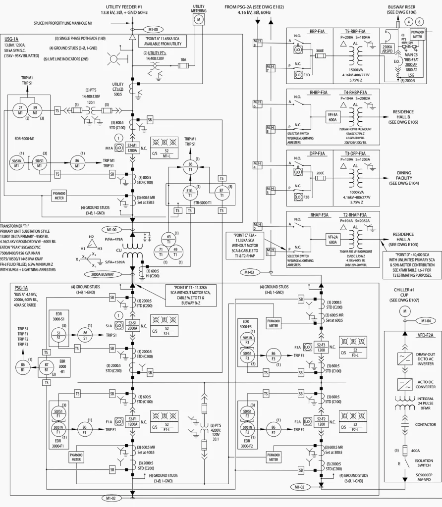
A single-line diagram is a simplified diagram that shows the electrical connections and components of a power system or electrical distribution system. Here are the basic components of a single-line diagram:
Power sources: Power sources are typically shown at the top of the diagram and can include generators, transformers, and utility power.
Circuit breakers and switches: Circuit breakers and switches are used to control the flow of electricity in the system and are shown as lines with breakers or switches symbols.
Transformers: Transformers are used to change the voltage level of the power and are shown as two coils with the voltage levels marked on them.
Load centers and panels: Load centers and panels are used to distribute power to various loads and are shown as squares or rectangles with the number of circuits labeled.
Electrical loads: Electrical loads are the devices that use electricity, such as motors, lighting, and appliances, and are shown as symbols or labels on the diagram.
Busbars: Busbars are metal bars that connect electrical components and are shown as straight lines.
The single-line diagram is a visual representation of the electrical system and is used by engineers, technicians, and electricians to understand the system and troubleshoot issues. It is also used for planning and designing new systems or modifications to existing systems.